|
|
|||||||||||||||||
|
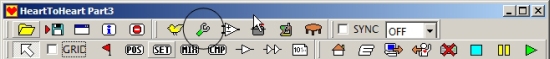
We now have a finished robot, but its still not quite ready to walk. As you will remember from the previous few steps where we installed all the servo arms and horns, they werent aligned perfectly, and some of them were even quite a bit out. Unfortunately, if we leave things like this, were going to find it hard to get good balance from the robot, and almost impossible to use any predefined sequences that anyone else out there has created. Time to re-connect the the 1HV to your PC and Heart 2 Heart, and go into the ICS mode (Interactive Communication System). The first job here is to set the stretch settings for each servo. The stretch settings control how much power is applied to each servo to keep it in the position you have asked it to move to. The higher the value (1-5) the more power is applied. There are numerous threads about problems with the KHR-1 robots having violent shake problems in the upper body, and the procedure to correct it. This process is designed to fix that in the 1HV by reducing the power to the upper limbs where they do not need as much power to maintain position. Fortunately no extra cables are required to do this. Open up H2H, and connect to the RCB using the correct COM port as before. This time instead of selecting sync, select Option. Its the icon that looks like a spanner with a green handle. |
 |
|
If the Option window doesnt open, then youve not connected to the RCB correctly, so turn the robot off and back on, then reconnect in H2H. As long as the option window did open, then select the channels in the ICS frame of the window then close the window. (Ch1-4, Ch6-8, Ch10-21). The settings are saved when you close the window so theres no save button to press. You dont need to change any of the other options from the defaults so just leave everything else alone. Back in the main window, select the ICS icon, which is meant to look like a servo, but looks more like a pot. |
|
The ICS window should now be displayed. If it is, then so far so good. Leave the window open, and power cycle the robot. Have a look at the RCB while you do this, and you should see the LED which is normally green will be red when you power on, then go back to green after a few seconds. As long as this happens, then youve successfully gone into ICS mode. If not, then go back to the start. (Close the ICS window, turn the robot off. Turn it back on, then re-open the ICS window. Powercycle the robot again). The first time I tried this, I didnt get the robot into ICS mode. After a power cycle and a retry, it successfully entered the ICS mode, and I could start setting the servo stretch settings. There are three sets of stretch settings for each servo, so following the table in the instructions, and set all the servos. Ch1-4 and Ch6-8 all use 3-1-3 and Ch 10-21 all use the higher settings 5-3-5. Once youre done, close the window to save the settings to the servos and then power cycle the robot to get back out of ICS mode. The last thing we need to do is to trim the servos, to correct any minor misalignments in the servo arms when we connected them to the servos in the neutral position. Select the POS, and then add a new POS element to the workspace the same as we did previously when setting the neutral position. This time, rather than setting the neutral, this time we set all the servo settings to zero. This will set the robot to a Flying Man position when we sync. Note: When you select the sync checkbox the robot will move VERY quickly. Id advise hanging the robot using the hoops on the shoulders rather than leaving it standing or trying to hold the robot. Have a look at the video I took of the first time I synced with the servo settings at zero to see what to expect. |
|
Ok, so if you look closely, youll spot that I didnt quite get that right. The right arm is not at 0. I still had it set to the neutral position, so it ends up flat rather than at the 45 degree angle it should be at. So, I adjusted the servo setting in the POS window, and was ready to start setting the trim. Select the Trim icon to start setting the trim. If youre not connected properly, the window wont open, however if youve just moved the robot to the Flying man, you should be fine. |
|
Theres little point in me trying to give you any settings here, as the settings I had were widely different to those in the manual, and will no doubt be very different for you. Just take your time, and get all the servos to align to the straight up position. Its difficult to stress just how important this is. Check the Robosavvy forums, and youll find a lot of people telling you that this is the most important part of setting up the robot, so take your time. Tiny adjustments can make huge differences to the stability of the robot, and the easy of which you can get it walking, and using predefined scripts. Theres lots of helpful diagrams in the manual, so spend some time looking through them, and use them as a reference for your own robot. There are alignment holes in all the limbs to help setting the trim position, so use them to help. Once youre happy, close the dialogue box to save the settings to the servos. Personally, I had to adjust the head, very little in the shoulders and some minor adjustment in the arms. I had some work to do to get the rotation in the hips correct as I had already noted earlier in the build. Then some small adjustments in the legs and feet. Even that took over an hour to get to the point I was happy. Next up, well set the home position, the startup sequence, and upload some sequences to the robot. |
|
[Home] [The Build] [Unboxing] [Start Build] [Shoulder and Knees] [Feet and Hips] [Creating the Chest] [Control Unit/Servo Setup] [Attaching Servo Arms] [Attaching Servo Horns] [Final Assembly] [Finishing touches] [Trimming the Servos] [Home Position & Startup] [Early Days] [Contact] |
|
© 2009 Neil Hutchison |