|
|
 |
|
|
With all the bits complete, its time we turned them all into a robot. I hope your fingers are ready for this, as theyll be sore by the end of it. I know mine were. So hairdryers are the ready, lets get started.
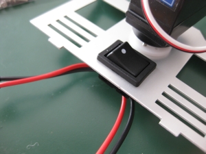
The first thing we need to do is to finish the head plate. The rectangular hole behind the head is designed to hold the power switch that so far weve just had dangling off the RCB-3. So disconnect it, and following the instructions, thread the cables through the hole, and seat the power switch in place.
|
|
|
|
Next up in the instructions are the cable tidies, so with a pair of snips and some sandpaper, I snipped them out of the plastic frames, and sanded down the burs. The instructions show where to put all the cable tidies, but dont do anything with them yet. Just put them aside. Do note the two different types of screws required. I initially used the wrong screw (the M2-8) which is a lot longer than the correct screw for most of them. Using the wrong screw could lead to the screw rubbing against the servo casing, and possibly damaging the servo. Fortunately I noticed my mistake as soon as I put the first screw in because it popped out the other side and surprised me. I ended up thinking that it was so unlike the kit that something wouldnt be just perfect that I went back and double checked.
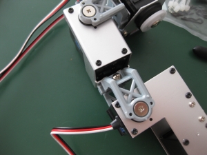
After all that, lets get back to putting the robot together. We need to put the arms together and put the hands on. The instructions show to put the hands on first, however given how tough it is to put the Servo Arm 700a base parts into the Servo Arms, I opted to put the rest of the arm together first, then put the hands on.
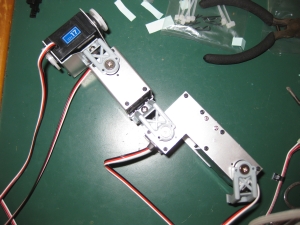
The arms use all four of the Bracket B (long) assemblies. Make sure when youre putting the arm together that the servos with the long cable are the bottom units (the ones the hands attach too) otherwise youll find the cables wont reach, and once your fingers hurt and the arms are put together, add your first cable tidy parts using the correct M2-6 self tapping screws.
|
|
|
|
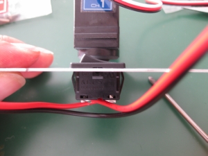
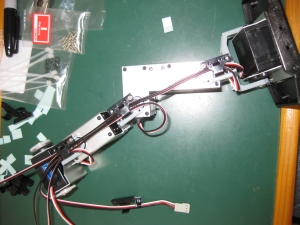
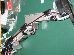
As you can see, the cables loop from the top of the controller, through the cable tidy, then neatly run up the arm. You can also see in the right photo the marking I made on the connector as I was getting fed up of sticking the cable identifiers back onto the cables.
Although the instructions show the cable tidy on the top part of the arm installed at this point, Id recommend leaving this until you have attached the arm to the shoulder.
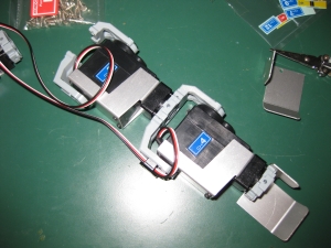
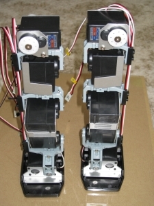
With the arms complete, and ready to attach to the shoulders we can put them aside for now and put the legs together. This really gives a sense of scale to the build, and the legs look great once theyre complete.
I started from the top at the hip, and worked down towards the foot. It seemed to me to be the most logical way to build the leg, but you may find differently. The one thing I will say is that the space at the foot to get your fingers in to connect the servo arm base to the servo arm is very tight.
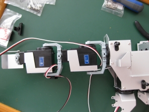
So from the top, the hip servos connected to the thigh servo ...
|
|
|
|
 |
|
|
|
The thigh servos connected to the knee servo ...
|
|
|
|
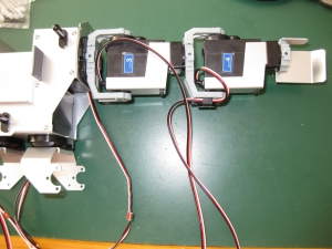
The knee servos connected to the ankle servo ...
|
|
|
|
The ankle servos connected to the foot servo...
|
|
|
|
And thats how we build the leg!
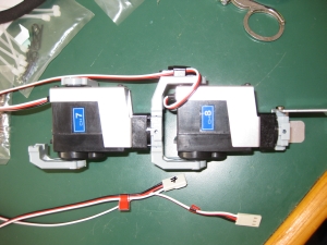
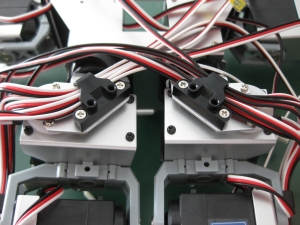
With the leg put together, we can attach the cable tidy and keep all the wires tidy. The right leg shown here has all the cables so that the black wire is to the outside. The left leg will have all the white wires to the outside. Here is a better closeup showing the routing of the cables. The cable from the foot is routed under the bracket so it travels across the top of the foot servo before being held in the cable tidy.
|
|
|
|
With both legs constructed, things are really starting to take shape.
|
|
|
|
At this point, its worth checking that all the connections between the servo arms and the servo bases have screws in them to keep them together. I noticed a little later that I had missed a screw in a couple of them.
Legs done, lets turn our attention back to the arms and get them attached to the torso. The instructions at this point are a little confusing. If you look closely at them they seem to show that the Servo Arm 700a base that you attached to the torso earlier is in a different position. Having gone back and triple checked that I connected everything exactly as described, I convinced myself that I had done things correctly, and just got on with attaching the arms. This is a particularly difficult section to connect as there is no way to get a pair of pliers onto the connection to help.
|
|
|
|
With the arms in place, only six screws per leg stand between you and having the legs in place too. Before attaching the legs, its a good idea to ensure that the hip servos are aligned to the neutral position.
With that done, attach the remaining two cable guides using the M2-8 screws and route all the cables from the legs through them.
|
|
|
|
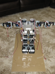
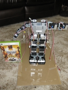
With most of the assembly done, its time to see what weve got. Ive added the xbox game case to give some idea of scale. As you can see, even with no power to the servos its remarkably stable, and quite happy to stand on its own.
|
|
|
|
With everything other than the head attached, we need to get the RCB-3 installed so we can tidy up the cables which are currently still just hanging around.
[prev] [next]
|
|
|
|
© 2009 Neil Hutchison
|
|