|
|
 |
|
|
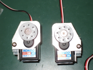
There are two types of connection onto the servos on the KHR-1HV. Weve already added a number of the servo arms, and now we need to connect servo horns onto a few of the servos.
The Horn is simply a thin circular mate with 8 holes to attach to another object. Anyone familiar with RC cars will be faitly familiar with this typw of connection. On the 1HV they are used for the hips, leg rotation, shoulders and head.
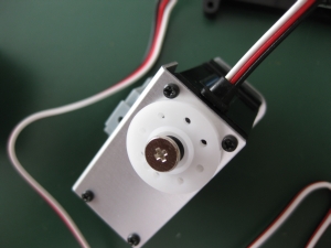
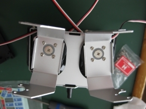
First up is the hip. Taking the two hip units we created earlier we will attach the horn to the gear of the servo. As with the servo arms previously, we want to set the neutral position, then try to get the holes lined up as close to central as possible. AS you can see from my picture, the alignment I get is not perfect, but as mentioned earlier, this will be adjusted by the trim settings later.
|
|
|
|
 |
|
|
|
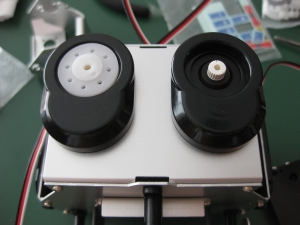
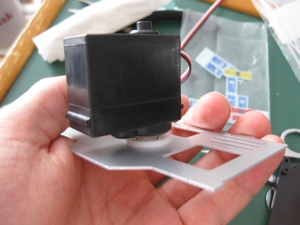
The other side of the hip has a free horn attached. This is similar to the servo horn, but without the teeth. Make sure you pick the right parts for the installation. Also, when adding the free horn, make sure its oriented the correct way. The side with the indent should be facing up, as this is where the screw head will rest against.
|
|
|
|
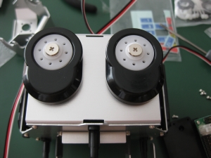
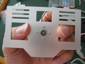
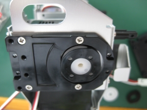
The next horn to be attached is to the base of the chest, and is the leg rotation section. For this, we need to add the Arm Spacer 700a before putting the servo horn in place and screwing it down. As always, make sure that the servo has been set to its neutral position before installing the horn.
|
|
|
|
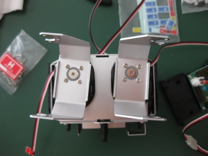
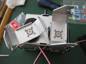
As you can see from the pictures, because we have no reference point, it is a little more difficult to tell whether the horn is aligned perfectly. Do the best you can before adding the aluminium Offset Arms B-L and B-R
|
|
|
|
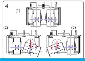
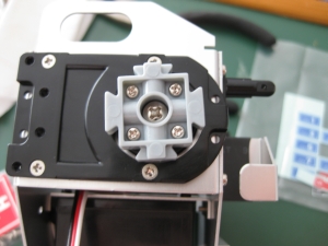
Now its much easier to see the alignment. As you can tell from the image above, the alignment was not perfect, however it was as close as I could get. The next thing is to check the range of motion. Checking with the diagrams in the manual to ensure that the full range is met. The arm on the left of the picture above did not get the full rotation as shown in the manual.
|
|
|
|
The range of motion here was far enough out that I unscrewed the left arm, moved it one notch on the sprocket and then re-seated it. That gave the full range of motion that the diagram showed, so I left it at that. The zero servo setting with that change is shown below. If you compare that to the original image above, the difference is clear.
Note: I realised after looking back through the images that the photo I took to show this difference had the chest in the opposite orientation to the previous photo, so Ive rotated it so that they are the same, with the black spacers at the top of the image.
|
|
|
|
 |
|
|
|
With the hips complete, its time to turn our attention to the shoulders. This is an interesting assembly, and requires some concentration. There are a number of parts here that it would be easy to install incorrectly.
First up, verify the servo neutral positions for Ch2 and Ch6 noting that they are 80 and -80 respectively, not 0 as most servos are. Then go ahead and install the servo horn, following the usual rules trying to get it as close to central as possible.
Once thats in place and screwed down, remembering to use the M3 toothed washer, you need to add the limiter cam. Check carefully the orientation of the lobe on this cam to make sure it is in the correct place. The cam has four pegs that go into the horn and hod it in place. Its not screwed in as youre about to screw a Servo Arm 700a base on top of it. The picture below shows the correct orientation for the right arm, and you can see the lobe on the top right before I pushed it all the way in.
|
|
|
|
 |
|
|
|
Check the correct orientation of the Servo Arm 700a then attach that through the four visible hoes in the limiter cam with M2-6 screws. Make sure the RECTO side is up, otherwise the screws will not thread properly into the horn, and will end up protruding which is not what you want. As the instructions state, This process uses screws normally used with plastic parts. This is not a mistake.
As you can see, again, the alignment is not perfect, however it is as close as I could get it. Repeat this for the left shoulder. (Note the alignment of the limiter cam is different for the left shoulder!
|
|
|
|
 |
|
|
|
Weve reached the last part that needs a servo horn attached, and its also the last servo that youve not used. That must mean it time to put the head on our robot!
This is one of the simplest horn to add, as it just goes straight onto the last 300mm cabled servo. Again check the neutral point before installing the servo horn.
Once the servo horn is attached, it is screwed onto the Top Cover_a. Again with the aluminium part, there is a right and wrong side, so check that the smooth side will be up, and screw from the wrong side into the servo horn which is placed on the right side of the cover.
|
|
|
|
As previously, given that this is the final installation of a part, check the range of motion. The head uses the full range of motion of the servo, quoted as 180 degrees, but as you find, its actually closer to 200 degrees, allowing the head to have the appearance of looking slightly over its shoulders to something behind it.
Next well start putting everything together into the final robot.
[prev] [next]
|
|
|
|
© 2009 Neil Hutchison
|
|