|
|
|||||||||||||||||
|
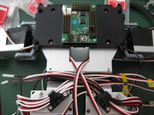
Before we can finish tidying up the cables, we need to attach the control board to the back of the robot. Four M2-6 screws takes care of that. |
 |
|
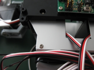
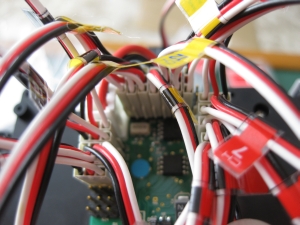
You can see the problem I had with the cable stickers in the photo above. The sticker for Ch13 is barely still attached. You may remember a while back that I mentioned the instructions told you to put 9 screws and not 10 into the back. Well even up to this point, theres still nothing going in the spare hole, so having a quick scan forward, there are some photographs showing the correct places to put the cable ties, and theres clearly a screw in there, so Im putting one in too. |
 |
|
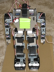
Now that Ive put that screw in, and that hole isnt bothering me any more, we can get down to putting the head in place. The head isnt secured with any screws, it just slides into place. The tabs at the back sit in slots on the back frame, and the protrusions at the front slide into grooves on the front of the frame. This is really difficult to seat properly, but dont try to force it or you could end up damaging either the head cover or the frame. When sliding the head into place, the cable from the switch to attach into the RCB-3 is taken out the back, while the cable to attach to the battery is routed out the front. Take care not to pinch the wires when you slide the head into place. |
 |
 |
|
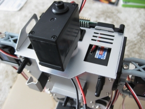
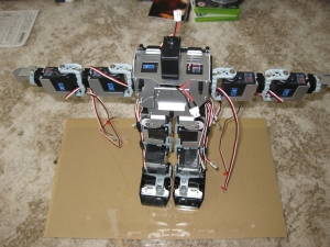
Not much left now. We just need to connect everything to the RCB-3 and start testing. Looking good. |
 |
|
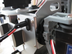
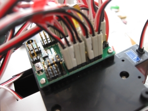
Going back to the PBC, its time to connect all the servo cables and plug the power cable back into the board. Each of the cables are connected with the black cable to the outside of the board. Since we have each of the cables labeled, its a fairly simple job to match the cable up to the correct pinout of the board. The pins run anti-clockwise from the right of the board, and the instructions show a very clear diagram. The board is also clearly marked on the PCB. With everything plugged in the board should look something like the photos below. |
 |
 |
||||
 |
|||||
|
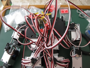
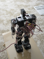
At this point, the instructions suggest using the cable ties provided to tidy up that mess of wires that Ive been left with. So far Ive decided to ignore that advice until I can test the movement of all the servos and check that I have enough slack in each cable. It means things are a little messy, but I would rather that than find I have things too tight and restrict movement or damage a cable when I start testing. The instructions also tell you to add the chest and rear covers now that the cables are all taken care of. Since Ive not taken care of the cables, Im leaving this for the moment. The last thing to do is to attach the battery and locate it in the cradle. |
 |
 |
|
Well thats us pretty much done with the build. Time to connect the complete robot up to Heart 2 Heart and get the servos trimmed to fix any minor delta between the perfect alignment we want and the current position the servos are in. |
|
[Home] [The Build] [Unboxing] [Start Build] [Shoulder and Knees] [Feet and Hips] [Creating the Chest] [Control Unit/Servo Setup] [Attaching Servo Arms] [Attaching Servo Horns] [Final Assembly] [Finishing touches] [Trimming the Servos] [Home Position & Startup] [Early Days] [Contact] |
|
© 2009 Neil Hutchison |