|
|
|||||||||||||||||
|
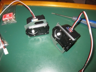
Next up are the shoulders. This uses the two larger servos in the kit and is a little more involved. Grabbing the two 4024 servos, theres two screws here which are removed and never re-used. A little bit of time is required in this step to make sure that the aluminium brackets are attached to the servos correctly. The orientation here is important so that the left and right shoulder will fit correctly. I spent a good five minutes looking at the diagrams and verifying that the orientation was correct before putting these subassemblies together. Take the Shoulder Frame L_a and R_a along with the Arm Spacers and follow the instructions to end up with the two shoulders as below. These two servos dont come with the cables already attached, so its back into the parts bag for the two connector cables which need to be carefully inserted in to the slot on the side. The cables are marked with a flange so that inserting them incorrectly isnt really a problem, but there is a fair amount of play in the hole, so making sure that the cable is being seated correctly on the pins is required. |
 |
|
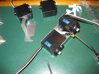
At the start of the instructions you are told that it is advisable to use the transfers provided to label each of the servos and cables to make identification easier. The diagram that is given isnt very clear. Ill try to provide a better one as I go, but at least from this step, the servos are labeled at the top of the instructions page, and is easy enough to add at this point. So for at least the shoulders Ive now labeled them. You also get small tags to allow you to label the end of the cable itself so Ive also done that. The instructions seem to jump about quite a bit in terms of what you build when, so now its onto the thigh and knee. This is a fairly big assembly and I certainly think it gives the 1HV its distinctive gait. One thing to note during this part is that the curved slots in the aluminium pieces are fairly tight so you need to be careful not to bend the aluminium or to damage the servo casing. You need the left and right Leg joints plus four servos. Note that two short cable and two long cable servos are required. |
 |
|
This is the first of the parts where the servos are labeled so as you can see Ive added the stickers and the end of the cable. One tip here is to mark the connector on the end of the cable with the servo number using a marker. I found that the stickers have a tendency to want to peel off, and werent a very reliable way to mark the cables. Creating the two main leg elements doesnt take too long, the only thing to watch is that when you are adding the side plates, make sure that the side with the indent on the outside. I stopped here as a good end point to Day 1 of the build. |
|
[Home] [The Build] [Unboxing] [Start Build] [Shoulder and Knees] [Feet and Hips] [Creating the Chest] [Control Unit/Servo Setup] [Attaching Servo Arms] [Attaching Servo Horns] [Final Assembly] [Finishing touches] [Trimming the Servos] [Home Position & Startup] [Early Days] [Contact] |
|
© 2009 Neil Hutchison |