|
|
|||||||||||||||||
|
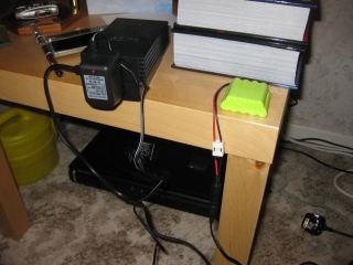
The first thing in the instructions, after two pages of cautions and warnings, are the instructions to charge the batteries. A full charge can take up to 23 hours, so best start that before doing anything else. Im not planning to build the entire robot in one sitting, but best to be ready when I come to start testing those servos. |
 |
|
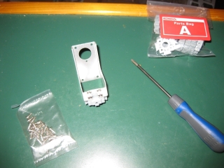
Given that this is a Japanese kit, the charger is a 110v supply. Fortunately, given that I have a number of electrical items that run on 110v, Ive got a stepdown box that will take the 240v in the UK, and give me the 110 that I need. Although you cant really tell from the photograph, it is shaped like a PS2. No, I dont know why either, but it does the job, so Im not complaining. With the battery plugged in to charge I can get started. Having made a lot of kits in the past, I now know better than to skip the step that gets you to check you have all the components before starting. So following through the 5 pages of parts, I check that I have everything, and also take the time to familiarise myself with all the bags of screws. Theres a lot of different types of screws used, all of which are very small and fiddly. Next up on the list is to remove a large number of the casing screws from a number of the servos. This is part of the preparation, however since Im not doing the build in one sitting, and dont currently have a dedicated workspace that I can leave everything set up at, Im going to skip this and only remove the screws when required. Im also fairly obsessive, and try to make sure that if I remove a screw, it goes back into the same location it came from. Its not necessary, but thats just me. So first up on the build list is the two upper thigh joints for the legs. Following the instructions carefully, and double checking the correct orientation of the servo arm before screwing anything together, you end up with the brackets to hold the servos for the thighs. We need two Servo Bracket Bs and two Servo Arm 700A base. |
 |
 |
||
|
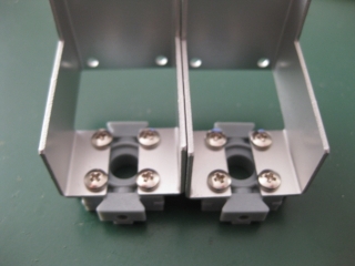
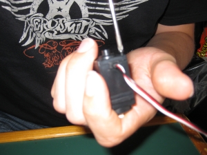
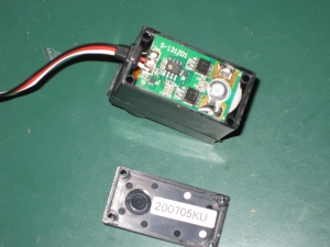
The resin parts that you are screwing into are fairly solid, and the self tapping screws do take a little bit of work to put in. A good screwdriver and some patience is required. Better to take a little more time now and make sure that everythign is ligned up correctly, rather than make mistakes, and weaken any connections by having to re-screw things later. Having created both mountings, the servos need to be attached. This requires un-screwing of the casing screws, then re-using them to attach the servos to their respective brackets. Im not as brave as Limor was about taking the servos apart, so if you want to see the inner workings of the servos have a look at his assembly guide for the KHR-1. For this we need two 788s with the 300mm cable. |
 |
 |
|
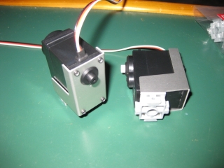
As you can see from the images, the aluminium brackets are very precisely machined, and as with all the parts in the kit, are of a very high quality. |
 |
|
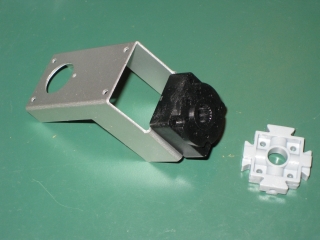
With the two servos attached to their aluminium brackets were done with the thigh assembly and ready to move on. Next up is the arm assembly. This is very similar to the thigh assembly we have just built. As is always the case, care needs to be taken when screwing the servo arms onto the brackets to make sure that the orientation is correct. The only real difference between the thigh and the arm is that an extra spacer is added as can be seen in the image below. We first add the imaginatively named Extension adapter before adding the servo arm base to that. |
 |
 |
|
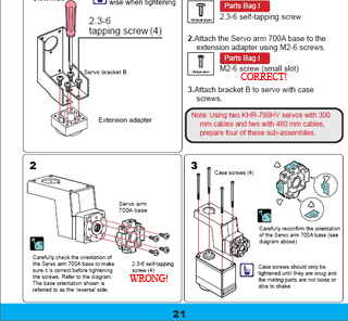
This is a perfect example of where following instructions blindly will lead you into problems. On page 21 of the instructions it tells you in the diagram to use the 2.3-6 self tapping screws to attach the grey servo arm to the black spacer. In the verbal description you are told to use M2-6 screws. If you blunder ahead and use the 2.3-6 as in the diagram, youll end up finding that not only do the screw heads not fit into the small gap in the molding that youre to, bot since they are slightly thicker than the M2-6 screws youll have made the holes in the spacer slightly larger than they should be. So, taking some time and thinking through what was being asked, I selected the M2-6 screws before doing anything and made the right choice. NOTE: Make sure to use the M-6 screws when attaching the grey servo arm to the black spacer! |
 |
|
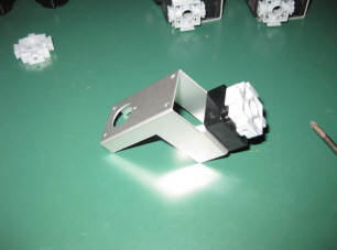
Four of these later and were done with the arm subassembly. Its worth noting here that two of these subassemblies are created with the short cabled (300mm) servos and two with the longer (480mm) servos. The lower parts of the arms clearly require a longer cable to reach the control board. |
|
[Home] [The Build] [Unboxing] [Start Build] [Shoulder and Knees] [Feet and Hips] [Creating the Chest] [Control Unit/Servo Setup] [Attaching Servo Arms] [Attaching Servo Horns] [Final Assembly] [Finishing touches] [Trimming the Servos] [Home Position & Startup] [Early Days] [Contact] |
|
© 2009 Neil Hutchison |