|
|
|||||||||||||||||
|
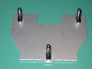
Next up is the Front Frame assembly. This is the chest of the robot, and will be the main core of our robot. The front frame houses the supports for the shoulders and also the battery cradle. Again you have to admire the quality of the parts here. The aluminium is precisely machined, and beautifully finished. Its almost a shame that eventually well cover it up with the chest cover. The front plate has two sides which the instructions tell you that the front is smoother and can be seen with your fingers. Its not that hard to see even without feeling the surface which is the front. Its a far higher finish, and on my plate, you could see all the light score marks where the plate was marked up for cutting the holes. Having found the correct side, we need to attach the three body posts to the front of the plate. These will eventually hold the molded plastic chest in place, or the suit if youve decided to go down that route. |
|||||||||||||||||||||||||
 |
|||||||||||||||||||||||||
|
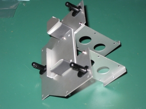
Next comes one of the trickiest parts of the build. We need to attach the battery cradle, and the rear struts which hold the shoulders (Servo Bracket A-a x2). One screw is required to hold all three pieces of aluminum on each side, before adding the other screws to hold everything in place. Aligning all three pieces and threading a screw, holding them together and not dropping the screw is a challenge. I felt at this point an extra hand would have been useful, but since I didnt have one, lots of interesting balancing moves were performed. Although I attached the battery cradle with its bottom screws first, hindsight would have said that attaching the two back pieces with their top screws first, then finally adding the one screw that goes through everything would have been the sensible way to proceed. At least youll not make the same mistake! Eventually, you end up with the structure below. |
|||||||||||||||||||||||||
 |
 |
||||||||||||||||||||||||
|
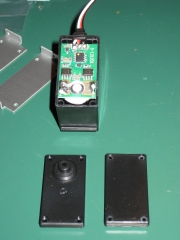
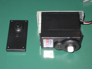
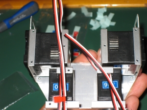
Next up were going to add the Lower Unit Assembly. This is the two servos that allow the legs to have their hip rotation, which lets the 1HV turn without dragging one leg round while moving the other. The first step here is to completely remove the backs of two of the servo cases. Unlike previous kits (the KHR-1 for example) where you had to chop off the back connector on the servo, this time Kondo have supplied us with two plain backs which are exactly what we need here. Once weve replaced these we can start to put this part together. These backs are a very tight fit. It takes a lot of force to get these to snap into place. |
|||||||||||||||||||||||||
 |
|||||||||||||||||||||||||
 |
|||||||||||||||||||||||||
|
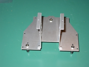
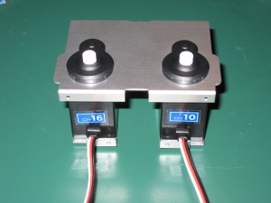
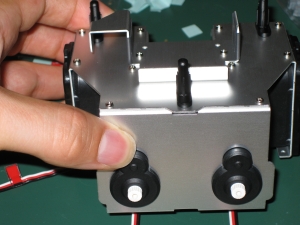
Once the backs have been replaced, an aluminium plate C-R and C-L is attached to the flat cover using the servo screws. These have notches cut out of them for the left and right, so you need to pay attention to the correct orientation of each piece. Next we attach a much larger plate over the front of the servos. It will come as no surprise that the fit here is very tight, so take care when attaching it. |
|||||||||||||||||||||||||
 |
 |
||||||||||||||||||||||||
|
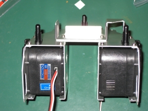
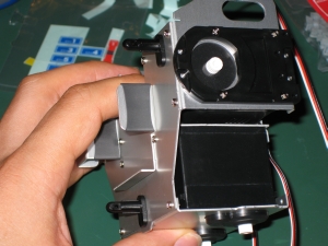
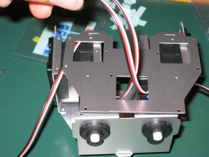
This top plate isnt screwed to anything yet, but given how tight the fit is, thats not going to be a problem! Now the final stage of assembling the chest begins. Weve got all the parts so its time to put them together. In this stage we add the shoulders, hips and attach them to the front plate. Adding the shoulders to the front plate... |
|||||||||||||||||||||||||
 |
|||||||||||||||||||||||||
|
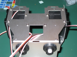
Then adding the hips... |
|||||||||||||||||||||||||
 |
 |
||||||||||||||||||||||||
|
Before adding the back plate which the control board will be attached to make sure the wires are routed correctly and arent being pinched anywhere. Also, dont make the mistake I did. If you look at the picture on the right, youll see the servo labels on the back of the two hip servos... watch closely as youll never see these again, and nor will I! |
|||||||||||||||||||||||||
 |
 |
||||||||||||||||||||||||
|
The two servo cables from the hips are pulled out through the bottom hole in the back frame, and as you can see those servo labels are going to vanish. If Id noticed that at this point, I could have moved them. The instructions show to add 9 screws to hold this back plate in place, leaving one hole in the bottom left of the frame which looks like you should put a screw in there without anything in it. At this point I trust the instructions and only add 9 screws. |
 |
|
Thats it for the chest. Next up we will calibrate all the servos and start adding the brackets to hold them all together. |
|
[Home] [The Build] [Unboxing] [Start Build] [Shoulder and Knees] [Feet and Hips] [Creating the Chest] [Control Unit/Servo Setup] [Attaching Servo Arms] [Attaching Servo Horns] [Final Assembly] [Finishing touches] [Trimming the Servos] [Home Position & Startup] [Early Days] [Contact] |
|
© 2009 Neil Hutchison |