|
|
|||||||||||||||||
|
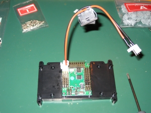
Before we can do much more on the assembly of the robot, we need to ensure that all the servos are at their zero location. So first up, we need to complete the Control Unit Assembly. Sounds very grand, but in reality, its just attaching the RCB-3 to the PCB base using 4 M2-4 screws and plugging the power switch into the board. In reality, you dont need to do this just now as were not going to attach it to the robot for quite some time, and it may be easier to leave the RCB-3 free while you follow the next few steps in the manual. I did however follow the instructions and attach the board and power switch. |
 |
|
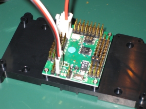
After reading through the information about servo movements and correct horn alignments its time to attach the PCB to your PC and set the servo neutral position for all the servos. Its important for this that the battery is fully charged, and youre going to be using the PCB to connect servos on and off for quite a while, so even though youre back to assembling the robot, I found that you were just as well to leave the PC connected to the RCB-3. Note: Ensure that before you attach any part to the servo that it is NOT plugged into the RCB-3. Its highly likely that as you screw the parts into the servo that the servo will move. If you do this when power is applied to the servo, you can damage it. Since you dont want to start with a dead servo, dont do it! Following the instructions carefully, attach the cable to the High speed port on the RCB-3, and ensure when you do that the black cable is to the outside of the board. This is true for all connections on the board. Regardless of what you connect, and what side of the board you connect into, the black wire of the connector always goes to the outside. |
 |
|
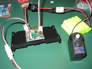
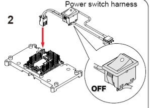
With the cables connected, its time to power on the board. Make sure that the power switch is off before connecting the battery. (The off position is where the white spot is up) When you turn the board on for the first time, windows will recognise it and go through the driver install. There are drivers on the CD that came with the 1HV, so this shouldnt be a problem. Its probably worth me pointing out here that Im a MAC user, so Im running Windows using Parallels on the Mac with no problems. The USB->Serial adapter is recognised, and Ive had no problems at all in using H2H through parallels. I have verified the usage on a PC and theres no discernible differences, so if youre like me and an Intel Mac is your default environment, then dont worry. Things will work just great! |
 |
|||
 |
|||
|
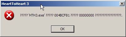
With the drivers installed, its time to start up Heart to Heart 3 for the first time. There is a Japanese version on the CD, but English versions can be found here. Each time I start up H2H, I get a popup in question marks (probably Japanese but no font support) with an OK button. I have no idea what it says, but clicking OK starts H2H, and Ive had no issues, so Im guessing whatever it is its more informational that error related. |
 |
|
Your first challenge with H2H is working out what COM port the USB-Serial adapter was installed to by Windows. It seems a little random, and unless you want to go hunting in the hardware settings, trial and error is the easiest way. From the drop down, select each COM port (COM1, COM2, COM3 etc) until the H2H reports COM ok. For me it was COM3, however it may be different for you. Once you have found it, select the SYNC checkbox, and youre now talking to the RCB-3. Ok, so its not the most exciting thing ever as its not going to do much just now but at least youre now talking. Follow through the instructions here to create a new POS object in H2H and set the servo neutral positions as described. I followed the instructions exactly, and set the positions for each servo. I also saved this as a neutral.rcb so that I could reopen it later if needed. This file can then be used when you set the neutral for each servo by connecting the correct channel to the corresponding pins on the RCB. So for any of the servos that are not set to 0 as their neutral position, you can just plug them into their correct port, and know that the value will be correct given that you have set it up here. Thats exactly what I did, however you may find it faster to always connect the servo to channel 1 and ensure the value is set in H2H before connecting it. Its up to you to find out what works best for you. Although the instructions are prefect, Ill add a little explanation here to try to help you understand what youre doing. Each servo needs to be set to its base point before attaching any servo connections. If you ignore this, when you turn the robot on fully built, its not going to go where you expect, and the servo locations may be random. Before attaching anything to the gear on the servo, ensure it is at the neutral position as described in the manual by setting the correct value in H2H, plugging the servo into the board, at which point youll hear it move, then disconnect it. Disconnecting it makes sure its set, and theres no power so youre free to work on it. It seems a little strange to do this, but it is the correct thing to do. With all servos set to neutral as described, its time to start adding the servo arms. |
|
[Home] [The Build] [Unboxing] [Start Build] [Shoulder and Knees] [Feet and Hips] [Creating the Chest] [Control Unit/Servo Setup] [Attaching Servo Arms] [Attaching Servo Horns] [Final Assembly] [Finishing touches] [Trimming the Servos] [Home Position & Startup] [Early Days] [Contact] |
|
© 2009 Neil Hutchison |